Conventional Fire Alarm Wiring Diagram
Even if you're not ready to take the plunge into fire alarm system design and installation just yet, you should still know the fundamentals in order to perform emergency work.
Difference Between Conventional and Addressable Fire Alarm
Class A wiring in a fire alarm system uses a primary signal path to all the devices, and if the signal path is interrupted, Class A wiring uses the Class A Return wires as an alternate pathway the signals. During fire, if a wire breaks, Class A Wiring provides an alternate route for signals to pass between field devices and the fire alarm panel.

Types of Fire Alarm Systems and Their Wiring Diagrams Fire alarm system, Fire alarm, Fire
One crucial component of any reliable home security system is the wiring methods and cables used for fire alarm systems. These systems serve as an early warning system, detecting the presence of smoke or fire and alerting occupants to evacuate the premises promptly.

Fire Alarm System Circuit Diagram And Explanation Zoya Circuit
Call us: 01773 764626. A Basic Guide to Fire Alarms and Fire Alarm Installations. Tecserv UK is a specialist fire alarm and security system installation company. It's part of our role to be at the forefront of knowledge. However, we also recognise that sometimes people that are new to the industry, or have been recently appointed to the role.
Fire Alarm Systems Wiring Diagram Addressable wiring diagram creator
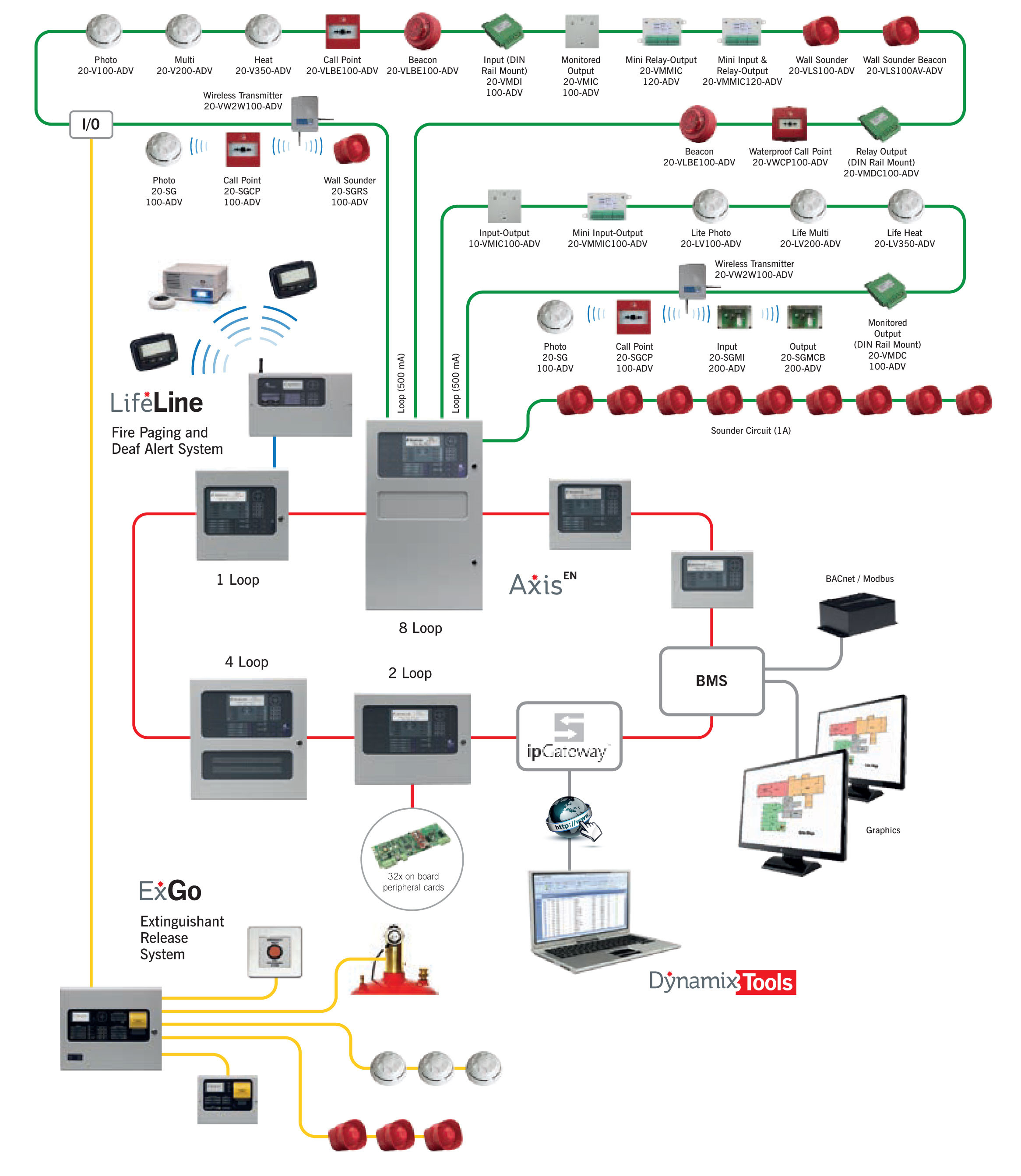
An automatic fire alarm system—typically made up of smoke detectors, heat detectors, manual pull stations, audible warning devices, and a fire alarm control panel (FACP) with remote notification capability—can provide early warning of a developing fire.

Addressable Fire Alarm System Wiring Diagram Pdf Wiring Diagram
of a fire detection and alarm system. Fire Alarm Control Units The fire alarm control unit (FACU), formerly called the fire alarm control panel (FACP), contains the electronics that supervise and monitor the integrity of the wiring and components of the fire alarm system. The FACU basically serves as the brain for the alarm system (Figure 14.2.

Fire Alarm Horn Strobe Wiring Diagram
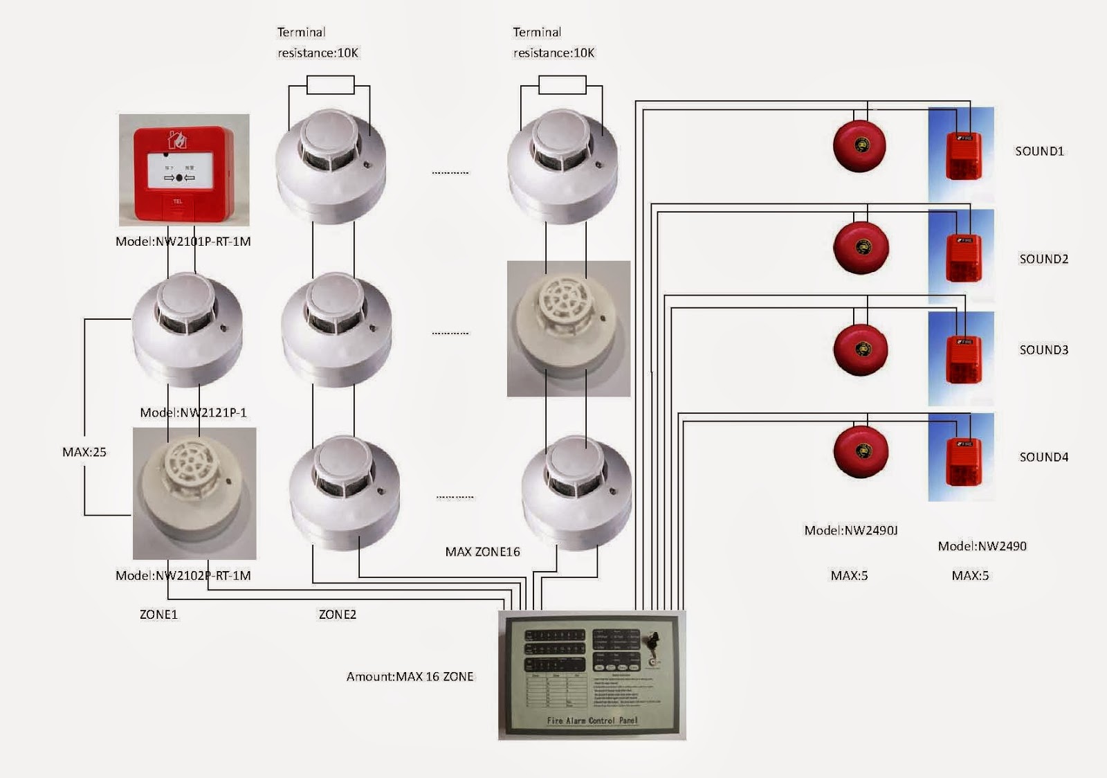
25 5K views 9 months ago #fire_alarm #fire_alarm_system #fire_system This video shows Fire Alarm System Conventional Wiring Diagram. The fire alarm system is wired using.

Fire Alarm Horn Strobe Wiring Diagram Free Wiring Diagram
What Exactly Does SLC Do? From Dumb to Smart - Enter Addressable SLC How to Design and Wire an SLC Circuit Keeping a Watchful Eye on SLC SLC Circuit = Smart Nervous System Sirens, Strobes, and Speakers - Demystifying NAC Circuits What Is NAC In Fire Alarm System What Does a NAC Circuit Do? Conventional vs Addressable NAC

Fire Alarm System Wiring Diagram ELECTRICAL KNOWLEDGE
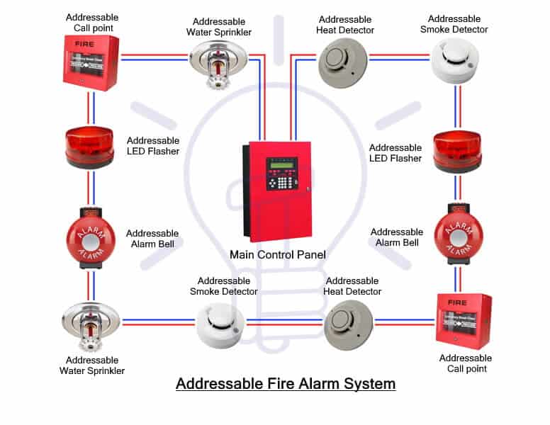
In the addressable fire detection system, the fire alarm system wiring schematic diagram as described below: Each detector has 4 connections (2 inputs & 2 outputs) The connection is done in the detector body. The detector body is given an address (serial addressing). In the addressable fire alarm system wiring the fire alarm control panel can.
Addressable Fire Alarm System Wiring Diagram Sample
Article 760 tells us how to install wiring and equipment for fire alarm systems, including all circuits these devices control and provide power to. What

Fire Alarm System Wiring Connection Diagram Convectional Fire Alarm Control Panel Fire
The process requires four basic steps: SELECTthe proper cable for the application; INSTALLthe cable properly; TESTthe cable to make sure it is free of shorts, opens, and ground faults; and TERMINATE the cable properly. BASIC CIRCUIT SUPERVISION There are two types of circuit supervision widely used in fire alarm systems today.
Fire Smoke Alarm System Circuit Diagram
There are a few different fire alarm wire types that you can choose from for your residential or commercial property: Different Types Of Fire Alarm Cable Power limited Fire Alarm Cables FPLR Cable Fire-power limited riser cable is a type of data cable that is limited to use in fire-rated risers.
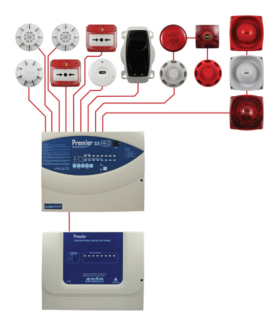
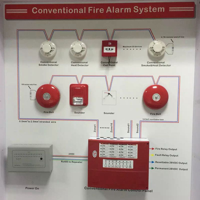
Conventional Fire Alarm Systems Typical Wiring Diagram Zeta Alarms Ltd
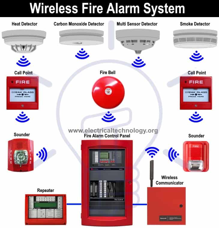
Fire alarm system is the combination of different components such as smoke detector, heat detector, carbon monoxide detector, multi sensor detector, call points, sounders, bells, relay module, repeater, annunciator, fire control panel and other related and optional security devices designed for fire alarm control system.
Fire Alarm Wiring Diagram Schematic
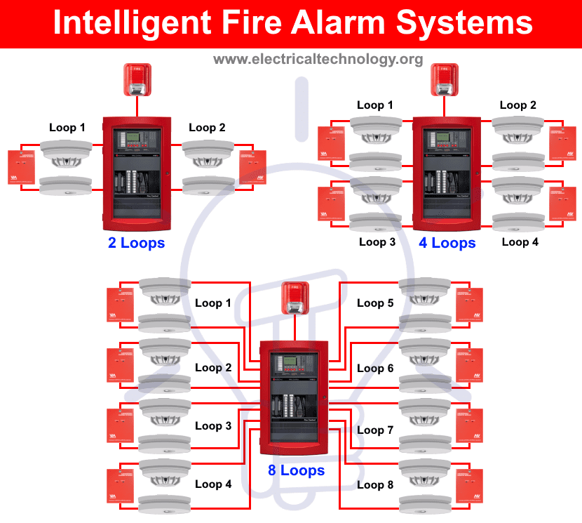
A wiring diagram for an addressable fire alarm system describes how the system is connected and how each component works together to detect and alert in the event of a fire. An addressable fire alarm system has components that communicate with one another and provide more detailed information about a fire than a traditional system.
Types of Fire Alarm Systems and Their Wiring Diagrams
Wiring your home fire alarm system can help to ensure the safety of your family and property. A correctly wired fire alarm system will detect the presence of smoke or heat in a room, triggering an audible alert that alerts you and others of potential danger.

Wiring Diagram For Fire Alarms
All wiring for fire alarm systems must be installed in strict accordance with NEC Article 760. National Fire Alarm Code rules address three major activities associated with fire alarm system installations, including their design, installation, and testing and maintenance. The rules for all three activities are interrelated and the code includes.
