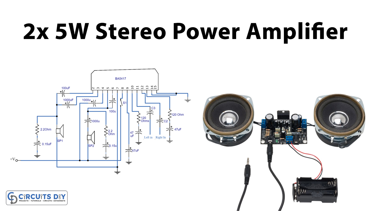
2×5 W Stereo Power Amplifier Circuit based on BA5417
ROHM Semiconductor is a Japanese semiconductor company that was founded in 1958. The company specializes in the design and manufacture of a wide range of products including power management, power devices, and analog and mixed-signal integrated circuits. ROHM's products are used in various applications such as consumer electronics, automotive.
2×5 W Stereo Power Amplifier Circuit based on BA5417
Class-AB monaural speaker amplifiers designed for automotive applications. AEC-Q100 Qualified Sound Processor IC designed for high-quality automotive audio applications. AEC-Q100 qualified audio processor ICs geared towards car audio applications. Variety of Audio ICs ideal for a wide range of applications.
Stereo Power Amplifier Circuit Based BA5417 IC »
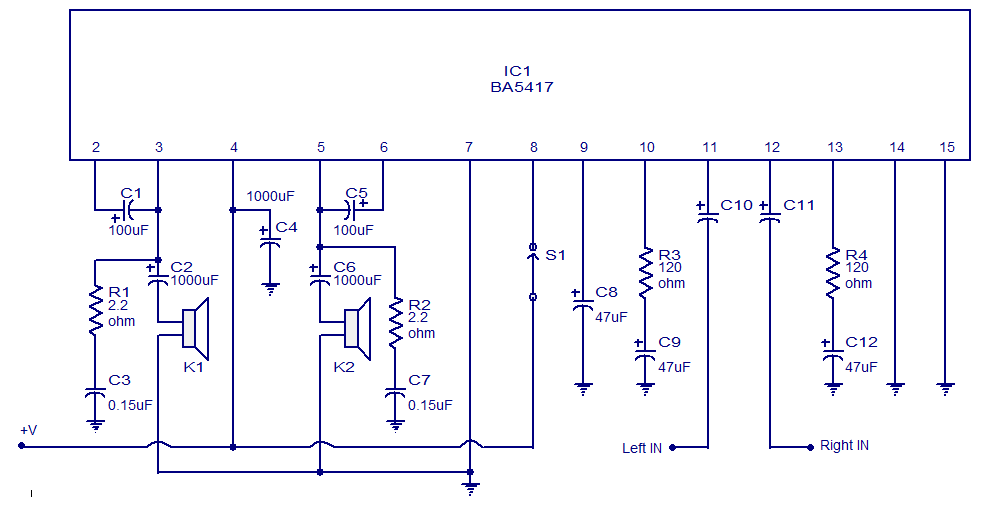
BA5417 Function Overview The BA5417 is a Dual OTL Monolithic Power IC with two built-in, high output speaker amplifier circuits. High output of 5W x 2 can be produced when VCC=12V and RL=3R and 2.8W x 2 when VCC=9V and RL=3R.
BA5417, BA5406 DIY Guide 5W Stereo Single Chip Power Amp
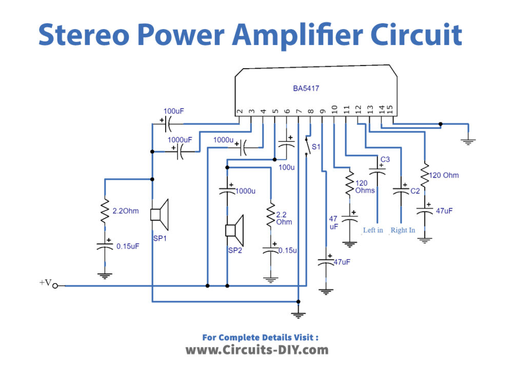
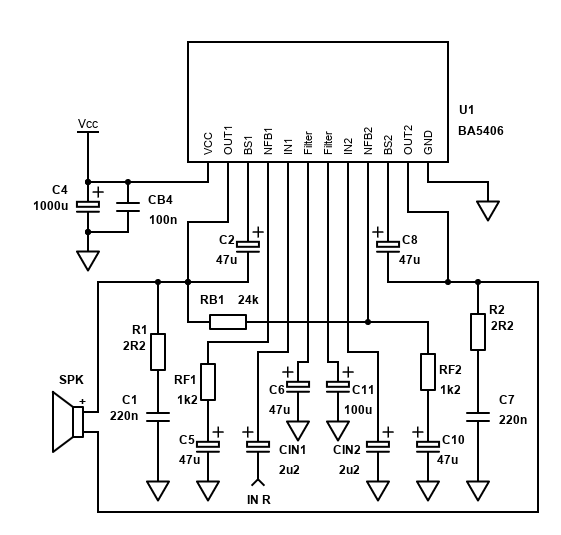
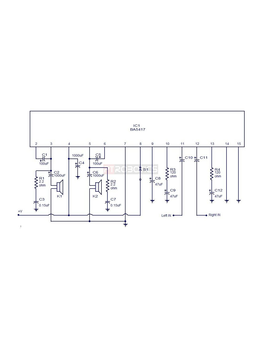
Circuit diagram. BA5417 stereo amplifier circuit Notes. Supply voltage range of BA5417 is from 6 to 15V DC. The recommended supply voltage for this circuit is 12V DC. The power supply must be well regulated and filtered. BA5417 requires a heatsink. The circuit can be assembled on a perf board without much degradation in performance.
BA5417, BA5406 DIY Guide 5W Stereo Single Chip Power Amp
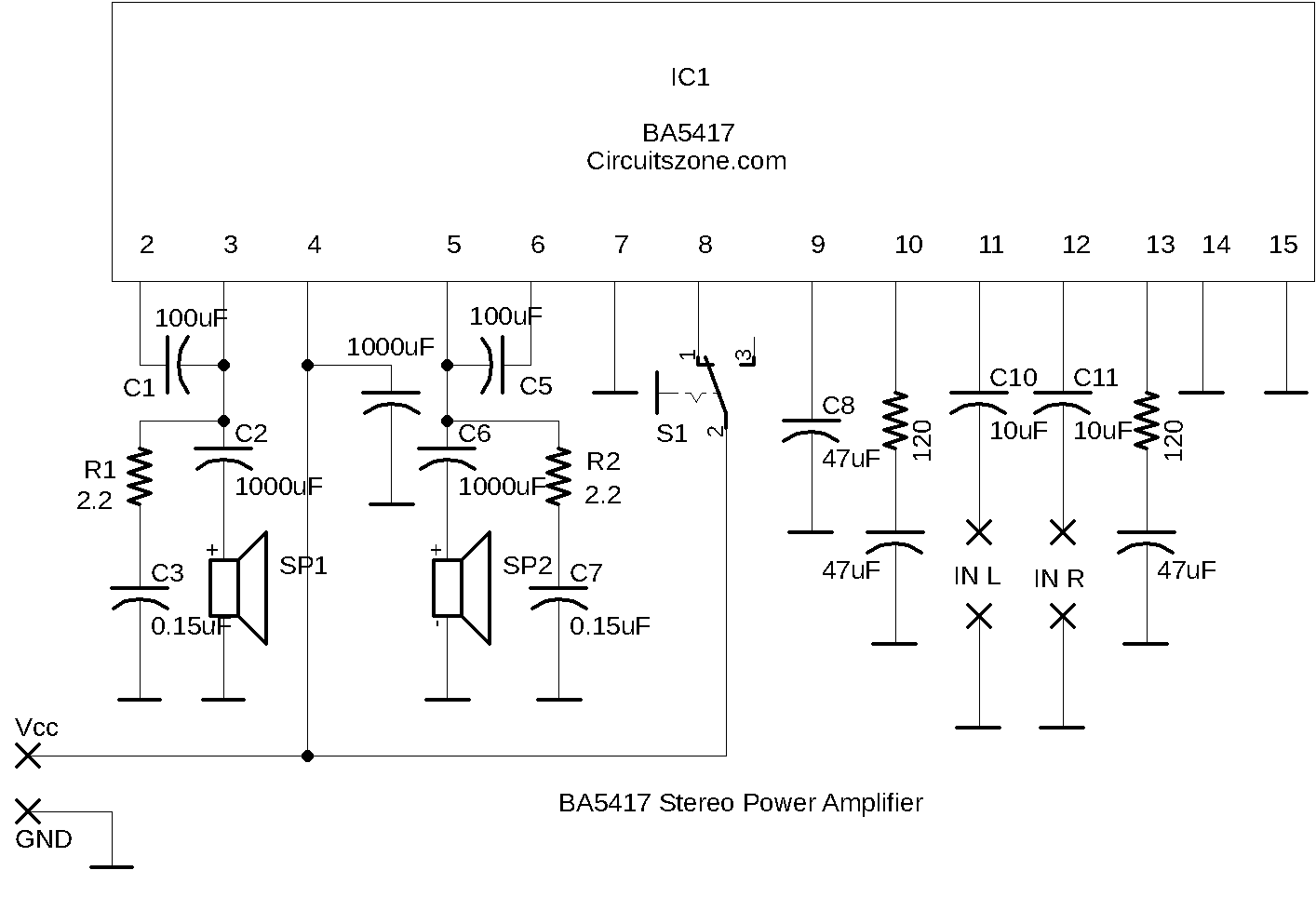
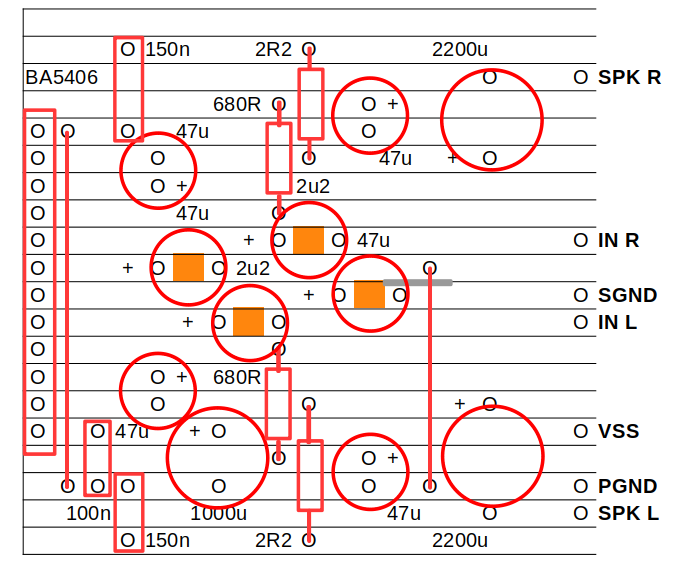
Circuit Diagram PCB layout TOP SILKSCREEN - BOTTOM VIEW BOTTOM LAYER - TOP VIEW Usage 1 Please set the switches STBY (Standby mode). 2 Connect Power supply, Speaker, and Audio Source. 3 Set Power supply 9V(Typ.). 4 Set the switches in order of STBY → NORMAL(Sound output mode) 5 Confirm the sound.
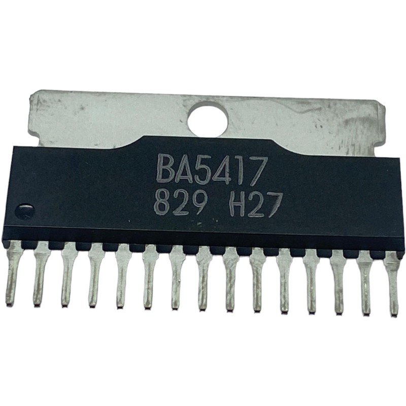
BA5417 Integrated Circuit
BA5417 Product details. The UTC BA5417 is a dual power amplifier of 6~15V-compatible for radio cassette/Mini compo players use. It is developed to equip with standby switching functions for excellent total harmonic distortion and other basic characteristics. * Operating power supply voltage range from 6V to 15V. * High output.
BA5417 de OEM Circuito integrado BA5417
Description The BA5406/BA5417 is a dual OTL monolithic power IC with two built-in, high output speaker amplifier circuits. High output of 5W×2 can be produced when VCC=12 V and RL=3Ω, and 2.8 W×2 when VCC=9V and RL=3Ω. The BA5406, which uses a high allowable power dissipation package, has a simple heatsink design.

BA5417 ROHM Amplifier ICs Jotrin Electronics
The BA5406/BA5417 is a d ual OTL monolithic power IC with two bu ilt-in, high output speaker amplifier circuits. High output of 5W×2 can be produced when V CC=12 V and RL=3Ω, and 2.8 W×2 when VCC=9V and RL=3Ω. The BA5406, which uses a high allowable po wer dissipation package, has a simple heatsink design.
BA5417 Stereo power amplifier
Circuit diagram Notes The supply voltage range of BA5417 is from 6 to 15V DC. The recommended supply voltage for this circuit is 12V DC. The power supply must be well regulated and filtered. BA5417 requires a heatsink. The circuit can be assembled on a perf board without much degradation in performance.
5x2 wattt stereo amplifier circuit using BA5417. Operates from 12V DC
The BA5406/BA5417 is a dual OTL monolithic power IC with two built-in, high output speaker amplifier circuits. High output of 5W×2 can be produced when VCC=12 V and RL=3Ω, and 2.8 W×2 when VCC=9V and RL=3Ω. The BA5406, which uses a high allowable power dissipation package, has a simple heatsink design.
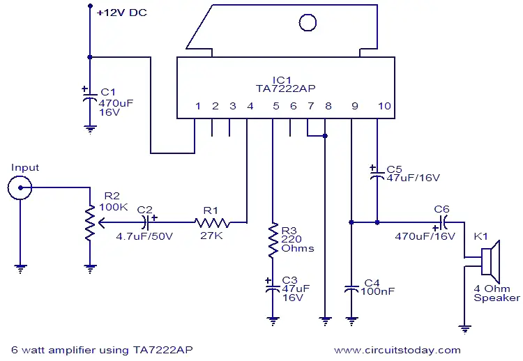
6W amplifier using TA7222AP Electronic Circuits and Diagrams
Description The BA5406 / BA5417 is a dual OTL monolithic power IC with two built-in, high output speaker amplifier circuits. High output of 5W×2 can be produced when VCC=12 V and RL=3Ω, and 2.8 W×2 when VCC=9V and RL=3Ω. The BA5406, which uses a high allowable power dissipation package, has a simple heatsink design.

Ba5417 Circuit Diagram
The BA5406/BA5417 is a dual OTL monolithic power IC with two built-in, high output speaker amplifier circuits. High output of 5W×2 can be produced when VCC=12 V and RL=3Ω, and 2.8 W×2 when VCC=9V and RL=3Ω. The BA5406, which uses a high allowable power dissipation package, has a simple heatsink design.

Wideband Wien Oscillator Schematic Diagram
1 Introduction to Power Amplifier 2 Hardware Components 3 BA5417 Pinout 4 Power Amplifier Circuit 5 Working Explanation 6 Application and Uses Introduction to Power Amplifier A circuit that increases the level of its input power to drive the different loads is known as the Power Amplifier Circuit.
audio stereo circuit Page 5 Audio Circuits Next.gr
Quick facts BA5417 Power output: 5W + 5W into 3 ohms at 10% 1kHz distortion with power supply 12V Power output: 6W + 6W into 4 ohms at 10% 1kHz distortion with power supply 15V Power output: 3.5W + 3.5W into 8 ohms at 10% 1kHz distortion with power supply 15V Power output: 2W + 2W into 8 ohms at 10% 1kHz distortion with power supply 12V

Elsie Circuit Ba5417 Amplifier Circuit Diagram Pictures
BA5406,BA5417 h Description The BA5406/BA5417 is a dual OTL monolithic power IC with two bu ilt-in, high output speaker am plifier circuits. High output of 5W×2 can be produced when V CC =12 V and R L =3 , and 2.8 W×2 when V CC =9V and R L =3 . The BA5406, which uses a high allowable power dissipation package, has a simple heatsink design.

BA5417 Stereo Power Amplifier Circuit Koleksi Skema RangkaianArtikel
Circuit diagram. BA5417 stereo amplifier circuit Notes. Supply voltage range of BA5417 is from 6 to 15V DC. The recommended supply voltage for this circuit is 12V DC. The power supply must be well regulated and filtered. BA5417 requires a heatsink. The circuit can be assembled on a perf board without much degradation in performance.
